as you may have noticed, the first clock was really one of the first projects i had ever done and i learned *a lot*. on top of that, my skills greatly improved over time. heck, check out the new timing circuit in the clock to see the difference. i've still got a lot to learn, but only time will tell. anyway, the hope here is to keep everything a lot smaller and a bit more modularized. plugs here and there and have a few pieces that can be disconnected from each other and reconnected so that they will be easier tested and one day fit inside a nice looking project box/display/something like that. that's the hope anyway...
once again, i'm using peter wendt's nixie clock page for reference and only posting changes and things i'm doing so you should check it out to see what's going on.
as a note about updates, additions and the dates: sometimes i put the date in to help keep track of where i'm at and what's going on update wise. i guess it's a little blog-esque. most of the time i update and fix errors and don't mention it unless it's bad and nasty.
|
11/12/2005: so, the first thing on the list was parts. last time i went around, ordered parts,
visited stores, drove here and there, ordered parts, drove here and there...it went on and on.
this time i tried to piece together everything i'd need and order it all at once and just
ordered it from mouser. they've got it all... but, for
some darn reason i still went to radio shack and bought a few things. weird i know.
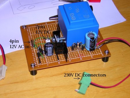
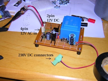
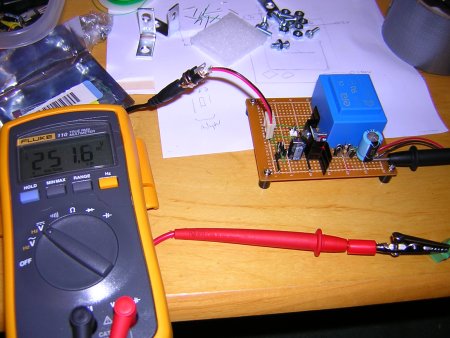
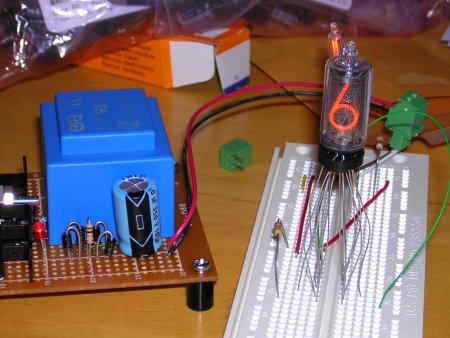
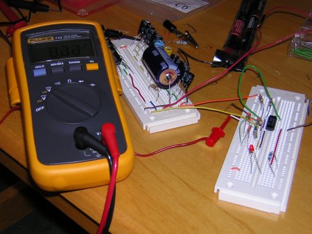
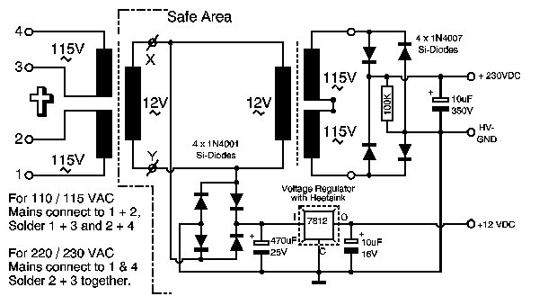
the parts arrived and the first attempt was the power supply. it's really the original design, but i did use a 115V -> 12V AC adapter so it would hang on the wall and not be stuck inside the clock. it takes up less space and is suppose to offer some safety advatages. on top of that, i stuck an LED on the 12V output (after the voltage regulator) so that when it's plugged in i'll know if it's on or not. here's the design and a few pics. 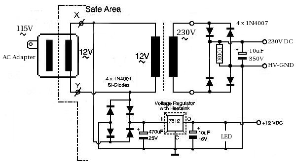 and the original
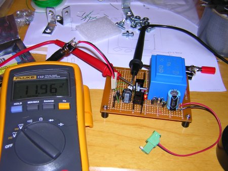
and the darn thing even tested out ok! the regulated voltage hits 11.96 which is pretty darn close to 12V and the step-up transformer is reading 251V because it's not under load. you'll notice that this time around i'm using a straight 12V -> 230V transformer instead of the 12V -> 115V and voltage doubler like i did before since i got a lot of my parts from radio shack before i discovered mouser (or any real dealer), and of course they didn't have any transformers like that. this time around, since i got all my parts from mouser, the transformer existed. either way, it works and you do learn a lot as to why it works. as i thought about which i'd rather do i figured this would be good to try out since i didn't do it last time. course, if i understand right, the output from the transformer is much cleaner than from a voltage doubler.
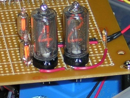
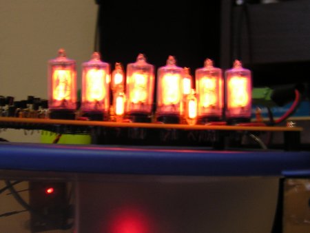
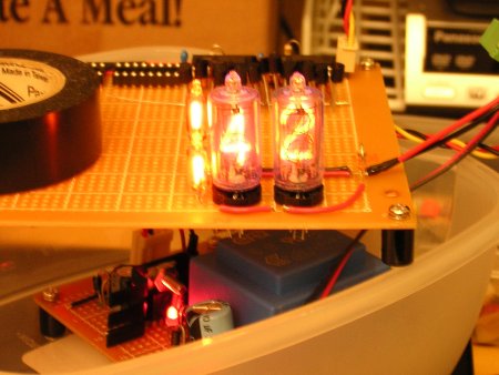
i ordered the tubes from sphere research again, and, once again, no problem. a call, a payment and like 3 days later the tubes arrived. this time i got the siemens zm1332 tube. a little bit smaller than the tubes from last time, but they were brand new this time and sure look nice. <g>
a grounding side note, since this got me last time... you'll notice that if you compare the voltage doubler power supply of the first clock and the diagram of this power supply (see above), there's a connection between the high-voltage ground and the low-voltage ground present. turns out, and i didn't know this originally, that ground doesn't equal ground. eg. low-voltage ground is different from high voltage ground. so, when i built the first clock the nixie tubes wouldn't light up even though everything was counting correctly. this was becaue the high-voltage ran through the transistor, but there was no low-voltage ground, so nothing happened. i gave my dad a call, talked with him a bit and he told me to connect the low-voltage ground to the high-voltage ground to solve the problem. i did, and wham, the problem was solved. the clock started working. so, was this a big "it worked one time"? nope. in the blinking tube movies below the 12V runs into the transistor and the only ground directly connected is the high-voltage. since this power supply connects low-voltage ground and high-voltage ground, it worked, just like it was suppose to. so, hopefully this makes sense to anyone but me and isn't complete bull. :) | ||||||||||||||||||||||||||||||||||||||||||||||||||||||||||||||||||||||||||||||||||||||||||||||||||||||||||
11/19/2005: after the power supply it's time to make the timing circuit. i actually
started last weekend, but it didn't go so well. everything else went amazing, considering
it was the first time at such a project in 3 years, but when i got to the timing, nothing.
so, back to work. but! this time around, instead of doing everything with a soldering iron
i used a pluggable breadboard. and that made it good. in about an hour it was working and
it looks like the reason last week didn't work is because the 4060 chip is blown and some of
the capicitors from the radio shack mixed box are bad. how'd i know last weeks chip was blown?
i found that the 4060 intakes 11.96V
and outputs ~6V...not to good. on top of that, it's hot as heck like it's just burning off
voltage. something isn't right with it. luckily i have a second one, so i used it and, sure
enough, with the plans i had originally, it works! and
it stays cool.
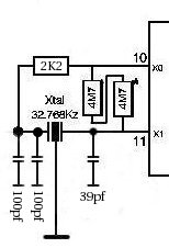
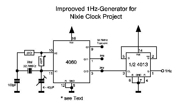
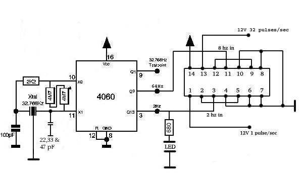 22, 33 and 47 pF are the different capacitors i tested it with and it worked with them all. your mileage may vary. note: timing has been redone a bit, so see below see the original afterward i soldered everything together and put the 4060 in and...nothing! what! i moved it back to the test and still nothing. then i found that it's outputing under 11V, around 10.5V to be exact. i have a bad feeling about this one too so i've ordered some new 4060s from a different manufacturer and we'll see if i just screwed them up, or if they're really that bad. |
11/20/2005: i decided to pull the 4060 from the old clock and test it out. and, what do you know,
it worked in the test setup without a hitch. the circuit i built needed a bigger capacitor, so i
changed it from 22pF to 39pF and it worked. the led blinked without a problem. so, either the
chips i got were bad, or i wouldn't trust them. the one that worked (and i've reordered) is the
NTE-4060B.
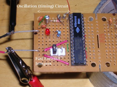
this circuit has the jumpers because i wanted to choose between two different fast forward speeds without having to resolder. the circuit is the same as above, it just has the jumpers inbetween the 4060 Q9 outpin and the flip-flop input pin 11 (i'll update it soon). the two speeds are 4 and 16. i was going to use 8 and 16, but the 4060 doesn't have 16Hz out. i'm sure there's a reason, but it seems weird... |
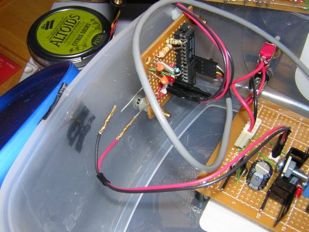
| 12/4/2005: i got the new nte4060 chips, put the old one back, inserted the new one and everything worked just like it was suppose to. yay! so, in playing around i bought a cheap plastic container so it could be the first box (it's just a test really). i drilled some holes, mounted stuff and we'll see how everything fits as we go along. the biggest thing is that i tested the nixie tube with the timer to see if it would turn on and off every second and how the tubes would look. as a side note, next time i put chips next together i'll put at least one space in between. the 4060 has flat edges, but the flip-flop doesn't. it buldges a bit and getting the two to fit next to each other like this might have been pure luck. but, it's working for now. <g> |
12/11/2005: oscillator changes at hand! originally i built the timing circuit, got it going and was
happy. but, it takes around 6 seconds to get going. so i decided i'd play with it and see what i
could do. i tried adding a bit more capacitance to the 22/33/47pf side of the crystal
(see above) and by
darn, that sped it up a hair. then, out of screwing around, i added a bit to the 100pf side. boy,
did that have a big effect! the start-up time dropped from six seconds to around 3 (btw- this was all
on the plug board). so i calculated the capacitor ratio between the two sides and found out it was
about 5.2. i don't know why i did this. it just seemed like a good idea.
since i have a 39pf soldered in i had to test it with a second 100pf capacitor, doubling
the pf on that side. wow! it dropped from a 6 second startup time to ~1 second. so, i sold myself
on it and soldered it in. that was saturday. then, on sunday, i figured it was a bit strange. why
did it work? so i dug around a bit and tried to refamiliarize myself with timing, crystals and
osciallation. if you're interested, i found some good links at ECS
Inc. (i have the tfc-3x8 crystal), wikipedia
and crystal oscillation, a pdf description
of circuit design, and an in depth discussion at google groups. anyway, i decided to look at the docs for my
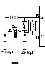
crystal and found the circuit design recommended varied a bit from
the original. so, i tested it out (see below) and on the
first round using a 22pf cap the crystal started osciallating in about 1 second! i switched to a 39pf
(note that both are 22 or 39 unlike 100 and 4-40)
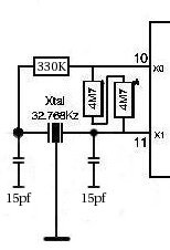
and it started the same, in about 1 second. then, i attempted to do the calculations to find out
what capacitor size would give me the "load capacitance" for the crystal as defined by the manufacturer
and came up with 15pf (see the pdf description, page 3 i mentioned above). so, i switched to that and
the darn thing starts up in less than a second! it's kinda crazy. here's the different layouts and even
movies to go along! and the original 6 second start can also be seen.
granted, this is all on the plug board and we'll see if i can solder everything together correctly...but it looks good. in comparison, it takes the version one clock a bit over two seconds to start up, so this is much, much faster. but, keep in mind, you should probably check out the docs for the crystal you have and see what they recommend for a circuit design. that's what seems to have solved the "how long it takes to startup" details. i guess we'll see for sure... |
|
12/18/2005: today i soldered the timing circuit together i had tested out in the plug board and
it was a success. the little led starts to blink in what must be around a half second and when i plugged
it into the test nixie tube you can't tell. you push the power button and it just starts flashing
each second. watch it if you want...
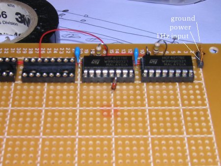
the layout is pretty similar to the original, but here it is, and it looks as though checking to see what the crystal manufacturer recommends will be a lot of help. the design might be just like the original, it might be like this and it might be different. i know, that isn't really helpful is it. :) (here's the doc for the ecs-3x8 crystals i've used) 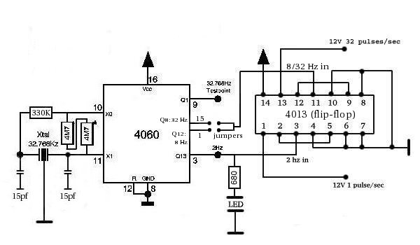 the current implemented circuit and, as i've mentioned, i wanted to start putting things in some container so i could see if they were small enough and get some idea of how the parts were fitting together. plus, it would give a good place to mount switches and the a/c adapter plugin. so i got a cheapy tupperware container and started mounting things inside. who knows if this will actually work, but we'll see... 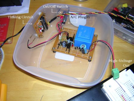 click for commented pic |
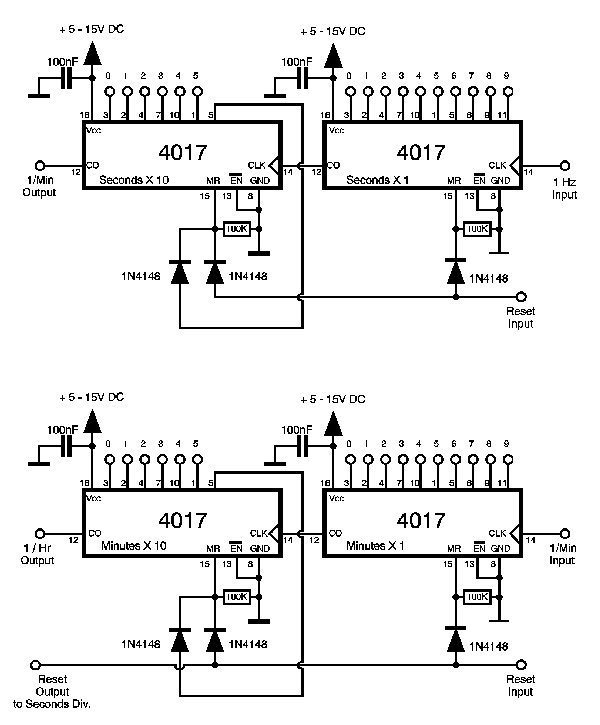
12/26/2005: now that we've got the timer going and the power supply ready it's time to
move to the world of counters and nixie tubes. so, first off, i worked with the seconds
decade counters. for weeks now i've been attempting to visualize, draw out and think about
how i'll lay this stuff out in an attempt to minimize wire criss-cross and help the
problem of all the little things that will infest the board. so, in a first attempt i
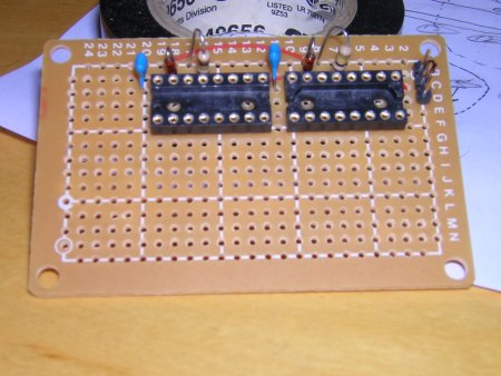
put the decade counters on a small board about 2x3 inches.
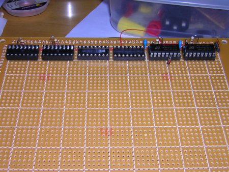
but, after i built it, and before i added all the good stuff to make the nixie tubes cycle, i decided that in order to link three of these together there would be to many wires and connections and it would be better to go back to the single board layout like i did before. so, the next day i worked on this i laid out a few more sockets and rebuilt the seconds decade counter area.
i did some tests and was able to see that it is counting corectly, just like the first time! if i held the volt meter on one of the pins of chip 1 (say 4) and waited for the DMM to blink 12V, then i would count "one-one thousand, two-one thousand..." and around the same time i hit 10 seconds, it would blink 12V again! then, if i go to the second decade counter i can see that pins are live for 10 seconds like they're suppose to be and i can follow from pin to pin and see that things reset and go from 0 -> 1 ... 4 -> 5 -> 0 just like it's suppose to. i even hooked up the test nixie tube i have in the plug board to the first counter so that evey ten seconds it would blink on for one second. then, i hooked it up to the second decade counter so that it would stay on for ten seconds out of every minute. i also tested the reset to see if that would work and surprisingly, it did. i think things went well today. :) since things are counting right it looks like it's time to add a few tubes and actually get things ticking... | ||||||||||||

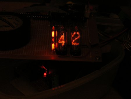
12/30/2005: i've had a nice surprise of off time during the week and been able to work on
the project. as of yet, the circuit hasn't changed from the original
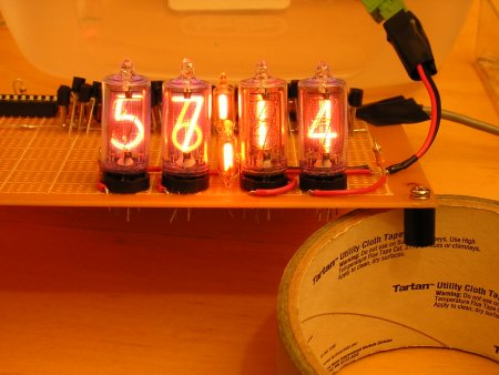
layout so i've plugged along and gotten the seconds ticking! i fought and fought about
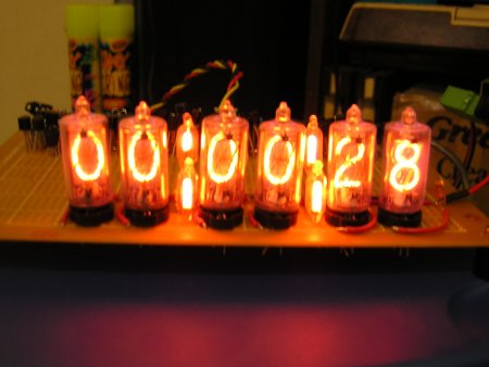
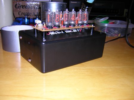
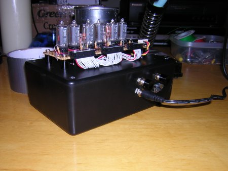
how to lay this out for now, and finally decided on the single board with the tubes at the front.
as you'll see though, there are two main sections: the counters in the back and the tubes in the
front. theoretially, when i finally figure out how i'll mount this stuff, the board can be split
into smaller pieces and the only thing i'll have to take out and redo is the connection from the
transistors to the tubes. we'll keep our fingers crossed... so, here's how it's starting to look:
i still haven't figured out how to take a decent picture, and you can sure tell from the above two shots of the seconds with the colon. the dark one is the "moving body" feature of the camera and the second is just without a flash. maybe one of these days i'll figure it out and get something decent up. the biggest thing that comes to mind is that i changed the resistor on the HV power to the nixie tubes. i was using 47K as a general one, but after rereading, referring to the docs and using the calculator on peter's page i changed to 33K. this is even a bit off. before the resistor the voltage measures 230V (Ub), after it was 145V (Ua) and the cathode current from the docs is 3mA (Ik). so, assuming i measured right and have it all right in my head then it calculates out to 28.333... i don't have any 28.333 K resistors so i used a 33K. interesting and we'll see what this does as everything seemed to test out the same after i replaced the 47K resistor with the 33K. so, a short update as the weekend is coming... but i know you wanna see what it looks like in action... |


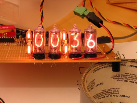
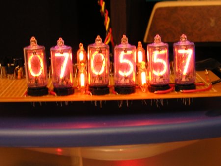
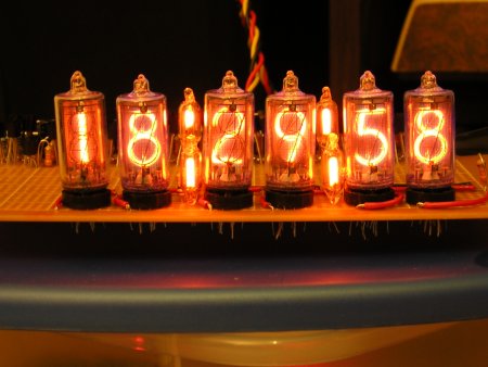
1/2/2006: the minutes have been added. more to come and i'll mention my "mistake" on the power to
the nixie tubes that was easily solved. :)
and the minutes in fast forward mode.... | ||||||
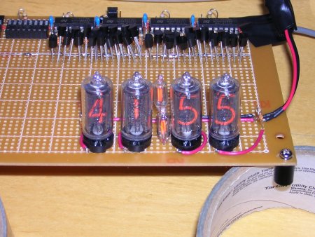
so what was the mistake on the power to the nixie tubes? somehow i had it in my head that the incoming voltage
to the nixie tubes was all shared through the same resistor. interestingly enough, it wasn't until the 4th tube
was hooked up that an obivious problem hit. the numbers were only partly lighting, for
example, the top bar of the five wasn't on, or the the lower piece of the number two. on top of this they were
so fuzzy that they were albout twice as wide. so, what was the solution? each tube has to have it's incoming
voltage through it's own resistor. DOH! and that makes sense. the current resistor is calculated for a 3 mA
draw (for theses tubes). with 4 tubes it would have been 12 mA and the resistor needed would've been different,
let alone with 6
tubes. ooops. so, theoretically, it could be done, but each time i added a tube i'd have to change the resistor
and it's probably much better for each tube to have it's own. here's the nixie tube reference drawing:
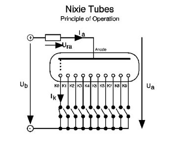 each tube with a resistor |
|
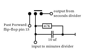
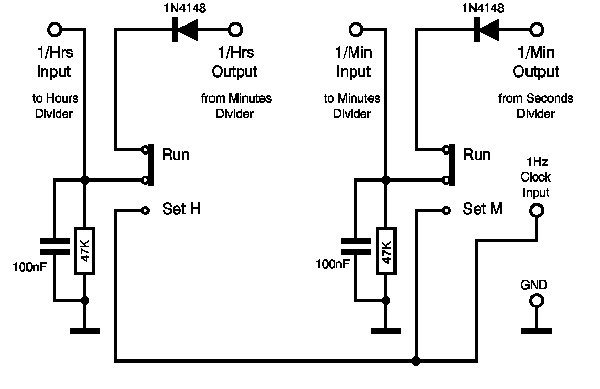
1/15/2006: some oddities with the fast forward switch popped up. it turns out that switches apprently don't do a
very good job of absolutely cutting off what they're doing and seem to short. and so were all on the same plane,
this is between the seconds divider output and the minutes divider input. by default it just takes what it gets and
passes it on for normal operation.
but there's a momentary switch that when depressed takes the output of the the second output half of the flip flop.
by default, this is 4 hz. if i change the jumper, it's 16 hz. when i first installed the switch so i could fast forward it mostly worked. sometimes it would jump ahead at what seemed 16 hz or even faster. then i noticed that if i depresed the button part way it would jump wildly, then once it was depressed all the way it fast-forwared at the correct speed. on release it even tended to jump from time to time. weird...very weird. i did some digging, wondering if the switch i bought was a piece of junk or the wrong type and found out that had i looked at the plans i probably wouldn't have had this problem. turns out that peter had this already planned. besides...i wouldn't have been able to come up with it. so after playing around a bit i found it worked wonderfully. i did have to increase the capacitor size though from 100nF to 10uF so there's definately something about the switch involved here, but it doesn't jump ahead anymore and seems to be behaving itself. here's the current solution:
|
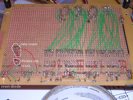
1/16/2006: we're getting closer to having the hours going. <g> after adding the next set of
colons i stuck in a switch so that you could choose between the two fast-forward rates i have
without having to change the jumpers. there's a picture of the silly little thing i had to
build below and an example in action if you really can't wait.
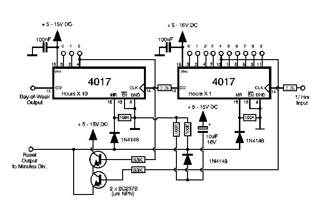
and after that came setting up the power on zero capability and the 24-hour zero function. once that was done and tested out it looks like we're ready to go and add the last couple tubes to see how it will all look for the first run. then comes the real nasty part. figuring out how to put everything inside a box so i can just plug it in and let it run. hmmmm... an interesting side note that might bite me later, but i don't think so. in the plans all the decade counters have a capacitor tied into pin 16, their 12V power input. well, the first five counters have this because by the time i hit the last one there were no holes left and i couldn't figure out where to put it. but it hit me that in this case the power in was a single line in parallel to each chip and each capacitor was hooked to that line and thus to each chip. so, i figured that i could get away without the last capacitor since all six counters should be sharing the five that are already there. so goes the theory in my head anyway... | ||||||
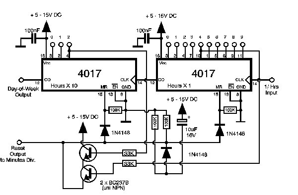
1/22/2006: and the first round of the clock is a go!
it ran for a few hours last night and it's been running all day today. now i'll run it most of the week and see just what kind of job i've managed to do and how it works when on for more than 5 minute test runs. <g> (3/12/2006: i realized i didn't have anything up regarding how the hours are put together, the clock is zeroed on start and it goes back to zero at midnight, so here's the schematic along with the original. note the only difference is the 2.2k resistor on input to both 4017s.) so, what's on the list? well, it needs a case and that's still a mystery. plus i've got an idea on how to make it battery powered so that when you unplug it, it will still work for a bit. the "bit" is of course the interesting part and we'll see just how long that goes. i'm also thinking about adding a couple extra things, like the ability to reset the seconds to zero, and maybe redo the fast-forward jumper area so that instead of two two-pin jumpers it's just a single three-pin jumper like between the seconds and the minutes. that would problably make the fast forward speed selector switch connection a lot nicer. but, the two big things are the case and converting 12V dc to 12Vac so batteries will work. that's an interesting one... here's a couple spots i'm eyeing right now: a 12V -> 120V schematic, a 12V -> 9V schematic, and some "simple" dc inverter schematics. we'll see if i can figure this stuff out since it's new to me. |
|
1/29/2006: and "most of the week" turned into the whole week! the clock's been running since about 10:00am
on sunday the 22nd until today, non-stop. wow...that's really kinda surprised me as well since i never
ran the first clock i built unless i was in the same room, like at work. i was
afraid it would catch fire and burn the building down. but, this one has been going strong (knock on wood)
and looks like it's passed the first test. <wipe sweat from forehead/>
the 12V dc -> 12V ac conversion is still up in the air though. luckily, i've gotten a couple ideas and i think one of them will work. details to come... |
|
2/7/2006: and we've hit over two weeks now! yup, it's still going. i had a little drive to turn it off and
play with a few things, but i just couldn't do it. since i was about to hit two weeks i scrounged up some batteries
and was able to hit 12V for the new idea that hit me in the head.
instead of powering the backup with a battery, why not do it with a capacitor? a really big capacitor! hmmmm... i originally got the idea from a supercap 9V battery i keep running into that i've seen at www.hackaday.com, in make magazine and other places around the web. so, in playing around, i bought a 4700 micro farad capacitor from radioshack and stuck it in parallel with a bunch of others i had sitting around. in parallel they all add together and the overall capacitance was a meager 0.00832 farad. short of the supercap, but it sure gave some interesting results to play with.
even with that the led blinked for over 30 seconds once power was removed. granted, it got dimmer and dimmer as time ticked by, but was still interesting to play with. once i connected the meter and was able to watch the voltage drop as time passed on i was able to see that although the led blinked for 30+ seconds, it only stayed above 10V for, at most, 5 seconds. but, once again, this is only .00832 farad, so we'll pretend it's a straight line and it did it for 4 seconds. that means that a 1F supercap would stay above 10V for 480 seconds. but, the led blinked and it continued oscillating (and the oscillator was the same as is used in the clock) for over 30 seconds so that would mean it could continue for around 3600 seconds. this is just guess work, but i like it. so, how do you implement it? that's the good question. digi-key has the cooper-bussman aerogel supercaps and these look interesting. the b series has a working voltage max of 2.5V but you can put them in series to increase this voltage. however, caps in series apparently does some really weird things to the actual capacitance total (although everything is actually equal in the end). i found a good explanation of caps in series and parallel. cooper-bussman also talks about the best way to create the series configuration in their application guidelines and as most of the electronics world is new to me and i need refreshing all the time i had to look up voltage dividing again and found something about the resitor voltage divdier. now, back to implementing it...ya...i'm still working on that... |
2/16/2006: i've been out working in mississippi and haven't worked on the clock. still working on the back up
super-cap idea, but nothing really to report. the only real thing is that the dog struck and the clock looked
dead!
while i was out i decided to leave the clock on so it could continue the wonderful history it was making. but, while i was out my poor girlfriend told me the dog got excited, like super excited, and wacked the coffee table where the clock is sitting and knocked it ajar. i told her to just turn it off and not to worry about it. biting my nails i wondered what had happened? did something short? did a wire come loose? did the high voltage short across and burn out, well, the rest of the clock? hmmm... so the day i got back i turned it on and sure enough it wasn't behaving. the timer worked fine as the led blinked like it was suppose too, showing that the crystal started oscillating. so i lifted up the board to look inside and noticed something...
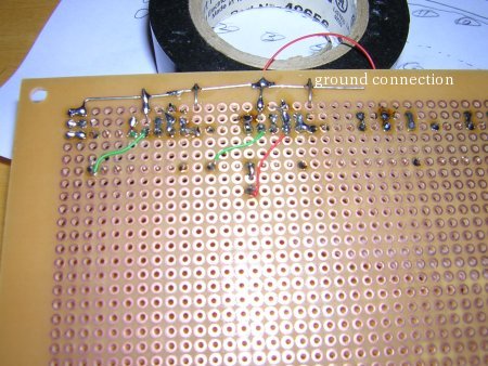
yup, the ground wire is ajar, not connected, no ground, nada. this is where the oscillator gets it ground and then passes the ground on to the decade counters and that side of the board ("that side of the board" meaning where the decade counters are mounted). so, if there's no ground, then that would definately be a problem. very interesting though that the led lit up and the oscillator started oscillating without ground none-the-less. interesting... but, once the ground was reattached it started up fine and we're back on track!
|
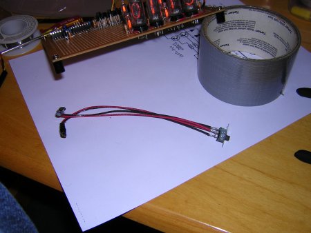
2/26/2006: this is short and i'll go into more detail later, but the alpha version is working although
it doesn't backup for very long and it's probably a "design issue" since i've no experiance at this. anyway,
here's the initial
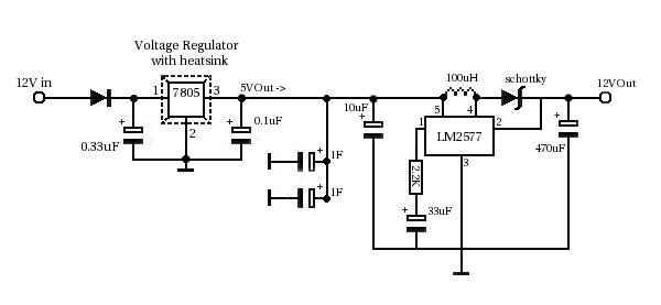
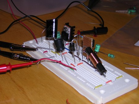
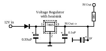
circuit i've put together and played with this weekend. in short, the whole idea is to take 12V in
and turn it into 5V since the ultra capacitors have a max voltage of 5V. you could do this with resistors
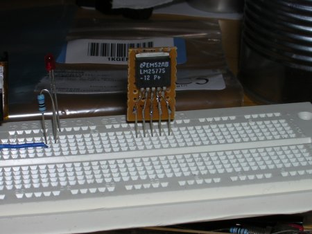
only, but i put the voltage regulator in becuase i don't trust myself. then, i used the LM2577 step-up
voltage regulator to turn it back into 12V. i know, i know...kinda silly. but it works. i tested it out
and was able to get 60 seconds of downtime with 1F and 180 seconds with 2F. now, it seems that something
is screwy and it should be longer. i forget where i did the calculations, i think it was at the
cooper-busman website,
but even then, that seems really short. i'm sure it has something to do with the circuit...
| ||||||||||||||||||||||||||||||||||||||||||||||||||||||||||||||||||||||||||||||||||||||||||||||||||||||||||||||||||||||||||||||||||||||||||||||||||||||||||||||||||||||||||||||||||||||||||||||||||||||||||||||||||||||||||||||||||||||||||||||||||||||||||||||||||||||||||||||||||||||||||||||||||||||||||||
|
3/5/2006: my head hurts...i've tried so many differing things in an attempt to lenghen the time
it's ridiculous. put this here, that there and most of it makes no sense since it's just stuff
i've made up because it make a little bit of sense. why did 2F only give 180 seconds?
the testing was all done on a second oscillator i have, built the same way as the first, just not directly plugged into the clock to make things easier. i measured the current draw to the oscillator and if it registered (the meter is analog) it was less than 10 mA, so it should be more than 180 seconds, much more. my mind was blank, so in a last ditch effort i scrapped the step-up and just plugged 5V directly in. it ran fine off 5V and when i disconnected it continued to run for just over 19 minutes. that was 19 minutes off of 1 F instead of 180 seconds off of 2 F. looks like the step-up is eating something horrible. so, i ditched it. then, to make a long story short i had to figure out how to use the caps with the clock, and i can't just use 5V there, so i tested out some 0.33 F caps i have in series so they would just work in the 12V setup and not need the 5V regulator or the 12V step-up. turns out, that if my math is correct, there is an overall capacitance of about 0.11 F and that kept the counters going for about 120 seconds! not bad for 0.11 F vs the 2 F last time. but, that's not the end of the story...the counters did continue to work, but everytime power was restored the clock reset to zero. this will get fixed! |
4/2/2006: it was just driving me crazy and i had to take a break. the reset was taking place no matter what
i did...and i tried so many different things it was pretty much just beating my head against the wall. so, it
was time to take a break. not that it's really related, but one of the things i did besides waste time, watch tv
and do about nothing was install enlightenment dr17.
i'm very impressed...but that's another story, so back to the clock today...
 in the many trials i decided that by doing this i'd switch to powering the clock from 12V to 5V since the counters and evrything would still work off of that. and, really all i'd need to do is change the voltage regulator from a 12V to a 5V and it would handle it fine. so, i did, and by some weirdness today i stuck a resistor in. yes, that lone resistor between the voltage regulator/ultra capacitor and the rest of the clock. and time after time the clock went to sleep for one, two, three and four minutes off a 0.33 F capacitor and came back on without zeroing or advancing irregularly like it had done before. to test it i took the resistor out and it wouldn't work. it would zero, or advance and show that it had been powerless for 4 minutes even though it was only 3. something weird. put the resistor back in and all was fine. then i stuck in a 1 F cap and it went to sleep about 13 and a half minutes without a problem. i was timing it and powering it back on when the voltage hit around 1.9V. it might go longer, but everything was working so well i just had to end it there. now there is one slight problem. when you turn the clock on it's a bit dim, and takes a few seconds to become fully bright. this is because the super-cap is "charging". why does this happen? yet something else to think on, but at least it starts ticking right away, still less than a second! |
6/10/2006: so after much thought i knew that i would have to redo the power supply to add in the capacitors
for backup. i would have to redo the timing circuit, just because...and in the end with all the switch additions
and little tweaks i have planned in my head, much of the decade counter section would need redone too. what does
that mean you ask? generation three! there's no doubt that i will build a new clock, and this one actually has
kept working so i've gotten use to it since i turned it on back in january. each time i thought about working on
it, i actually didn't want to because i was afraid i would break it and i wouldn't have it ticking away anymore. so, i
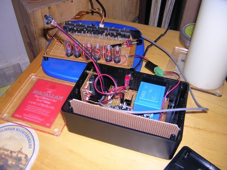
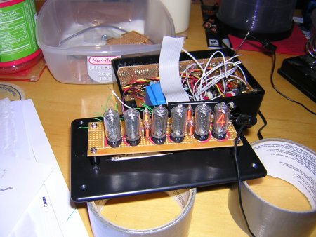
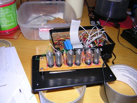
decided to box it up and see if i could figure out how to put it in some sort of "project box". boy...not an easy
task. somehow, and this really was a miracle, i was able to fit everything into one of the project boxes from
radio shack. thank goodness for the dremel!
| ||||||||||||||||||||||||||||||||||||||||||||||||||||||||||||||||||||||||||||||||||||||||||||||||||||||||||||||||||||||||||||||||||||||||||||||||||||||||||||||||||||||||||||||||||||||||||||||||||||||||||||||||||||||||||||||||||||||||||||||||||||||||||||||||||||||||||||||||||||||||||||||||||||||||||||||||||||||||||||||||||||||||||||||||||||||||||||||||||||||||||||||||||||||||||||||||||||||||||||||||||||||||||||||||||||||||||||||||||||||||||||||||||||||||||||||||||||||||||||||||||||||||||||||||||||||||


| and of course i had to start playing with something else: the dekatron |
| TIPS: | ||||||||||||||||||||||||||||||||||||||||||||||||||||||||||||||||||||||||||||||||||||||||||||||||||
| 1) you need to have some way to measure voltage and hz. i have a fluke 110 digital multi meter (dmm) that measures volts, hz, capacitance, resistance and a couple other things. it works great. this is very important as trouble shooting this stuff will be impossible without one. | ||||||||||||||||||||||||||||||||||||||||||||||||||||||||||||||||||||||||||||||||||||||||||||||||||
| 2) test along the way!!! if you build it (or even pieces) all at once, you'll never be able to figure out where the problem is. test and troubleshoot along the way. | ||||||||||||||||||||||||||||||||||||||||||||||||||||||||||||||||||||||||||||||||||||||||||||||||||
| Some refs: | ||||||||||||||||||||||||||||||||||||||||||||||||||||||||||||||||||||||||||||||||||||||||||||||||||
| - a fairchild 4013 pdf | ||||||||||||||||||||||||||||||||||||||||||||||||||||||||||||||||||||||||||||||||||||||||||||||||||
| - a fairchild 4060 pdf | ||||||||||||||||||||||||||||||||||||||||||||||||||||||||||||||||||||||||||||||||||||||||||||||||||
| - the zm-siemens nixie pdf (has the 1332) | ||||||||||||||||||||||||||||||||||||||||||||||||||||||||||||||||||||||||||||||||||||||||||||||||||
disclaimer: you are COMPLETELY at your own risk when trying to build anything referenced on this page. i am not your mom, think for yourself. if you can't, don't start the project.