just what is a nixie clock you ask? well there a couple of good examples including a gallery of clocks built by various people, and an on-line (the link has disappeared) clock. in short, it's nothing more than a clock that uses nixie tubes as a display.
nixie tubes were the predecessors to the led and were used in the 50's and 60's. they're vacuum tubes that (usually) use a fillament shaped as a number, or letter. when attached to a circuit the filament glows showing the appropriate number. that's it. if you're looking for more information, or explanations take a look at the above links, as they have quite a bit of info.
awhile ago i learned of these things from a story at memepool.com. i needed a new project, so i decided this would do. it helped that a friend was interested as well, and that the voltage involved is below the kilo-volt level (long story). so i did a little searching and found some directions for building one that looked reasonable. see, i didn't have any electronics classes in high-school or college so this is a very learn-as-i-go type of thing. i'll try and post updates, mod's to the above instructions, and if i can get a hold of a digital camera, some pics of what it looks like at various stages.
so...here we go...
for the blind: the original instructions. note that i'm only going to post mods to these, and not all of the instructions over again.
first off is the power supply. i've had a small amount of experience with these from my previous laser project. that one didn't really go anywhere, as i didn't want to play with 30,000 volts by myself. anyway, with the help of a book from radio shack and a college intro to physics book i managed to put together the supply, with a bit of changes.
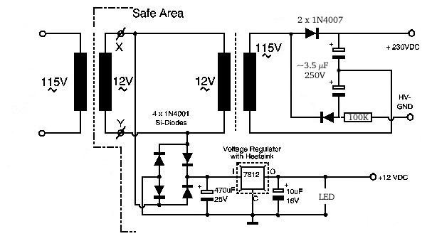
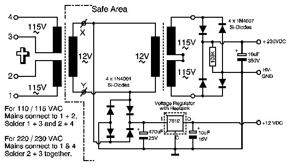
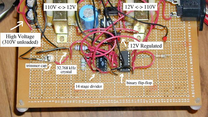
since peter lives in germany, his power comes in at 220V, while we in the US get our power at about 110V. so, i changed the transformers from 220 -> 12 to 110 -> 12, and put a voltage doubler in. so, as of now anyway, my power supply looks something like this:
the original
the diodes are the same as used in the other rectifier, while the capcitors are something i found at a wonderful surplus place in the area named wacky williy's. that's why there's a question of size. i don't know what size they should be, but this just worked. the resistor, in theory, is there to provide the ground. i've seen it in lot's of power supply drawings, it may not even be needed. experiment around, just remember that while the current is limited, 220V will still wake you up. think! and make sure you short the capcitors after you turn the power off, otherwise you'll get quite the little zap.
once i got the power supply up and cooperating i attached the little green led into the 12V side (shown above). this has two purposes: 1) it shows that the circuit has power, and 2) it looks neat! note that depending on what kind of led you buy, you may need to put a current limiting resistor in. check the box/bag for details.
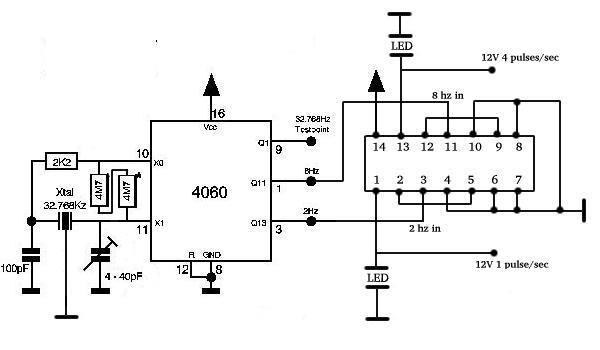
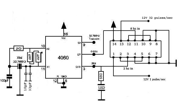
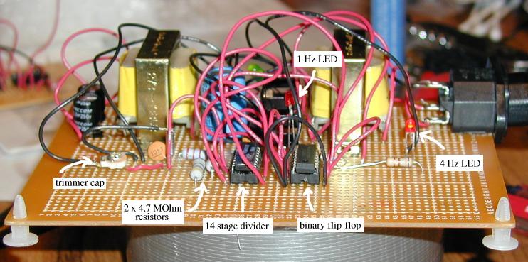
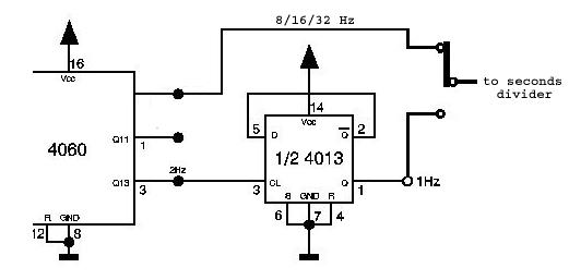
1 hz generator: so far, everything has been normal. i've got the 1 hz-generator built and working. i guess i did have to make one small change from the picture, but that was just adding a second 4.7 mega-ohm resistor (the bias resistor). once i did this, the crystal started right up! i also wired up the 8 hz output into the second part of the divider so that i have a 1 hz (normal) and a 4 hz (fast-forward) signal. later, i might change that to the 16 hz output for an 8 hz fast-forward. we'll see. after i got the crystal oscillating i attached an led to both outputs of the divider to see them blink. why? it looks cool. :) note that the chip pin-outs on the flip-flop divider may be different, so check you datasheet and make sure you're wiring the right stuff up. pins 1-7 & 14 come from peter's directions, the rest is me and my memory, so take that as a caution.
the original
note that the crystal is connected to ground. this is done by simply soldering a ground connection to the case of the crystal. as stated in peter's directions, you may only need to use one 4.7M ohm resistor, but i found that two in series (almost 10M ohms) worked great. to test your oscillation rate, use pin 9. on this you should get 32.768 Hz (if your meter has that many decimal places). mine doesn't, but it still read 32.76 Hz. close enough for me...
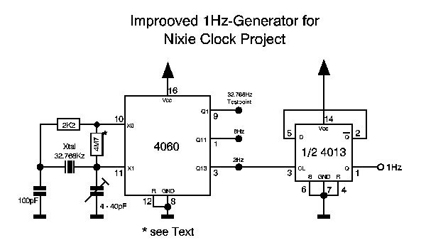
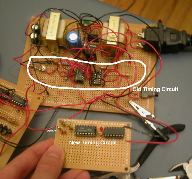
i decided to redo the timing circuit. my soldering has gotten better than when i started, and i knew that i could get everything to fit in a smaller space. while doing that i made a few changes to the circuit. the only one of major concern is dumping the 4-40pf trimmer capacitor. i didn't want to use a trimmer capacitor so i started with a 10pf ceramic cap. when the crystal didn't start oscillating i tried adding a 33pf one. it worked and being that i'm lazy i soldered it all in and left it.
for the old circuit and the original see above
the new timing circuit actually comes on line and starts oscillating in less than half the time of the original. but, that's probably mainly because of the size. as you can see there is quite a difference. you may have also noticed that i put led's in just about everything. i like blinking lights and it's a good way to tell that things are working w/out having to go back and test everything.
the hardest part has been getting the parts. most of the pieces you can get from electronic shops, but i say get it all at once from a big on-line shop. also, you may need to convert some of the part numbers in the instructions to NTE (a big electronic parts manufacturer) part numbers. they have an on-line converter just off their main page. note that the NTE-519, one of the diodes, will be hard to find and will probably be back ordered all over. so, if you find a bunch, buy a bunch.
i ordered my nixie tubes from a place called sphere research. the 32.768 khz crystals i ordered from mouser.com. they have a ton of watch crystals, but for reference i got 520-TFC3X8, an ecs watch quartz crystal, for $.30 each. buy a bunch. then, i bought a big bunch of stuff from action electronics. i just found them on the NTE web site and they seemed to have everything i needed.
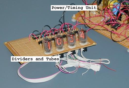
once we get to this point i have a couple pictures of what my project looked like before the new timing circuit. it's a bit more mind-boggling than the drawings, but i thought it would be nice to show how it was coming along, and what everything looked like for those that may not know what to expect.
 the crystal is hard to see...but it's there. |
 i wish i had a mpeg so the lights would blink |
so, i have made some progress, and unfortunately i don't have any pictures yet (it's my friend's camera). however, i do have the seconds done. it counts from 00 -> 59, and even rolls over back to 00 when it's suppose to! yeah!
i wasn't able to get any pictures of it until i had done some more work, so here's the clock in it's two distinct pieces complete with minutes and and seconds (my finger is on the fast forward button). The first piece, described above, is the power supply along with the actual oscillating crystal powering the clock. The second piece holds the seconds, minutes and hour (soon to come) dividers along with the nixie tubes as described in the section "Driving the Nixies" (see the original directions).
 minutes and seconds running along |
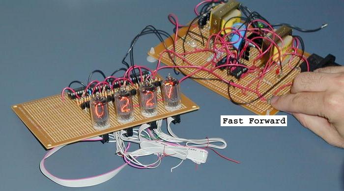 time to fast forward |
i guess this piece is really where you start to test your patience, and your soldering ability. once you start attaching the counters to the transistors and the nixie tubes it starts to get really, really tight. i got some 30 gauge wire for this. now, while it is a major pain to get the length right, and then strip the ends of the damn things it makes it much, much nicer on the underside. in fact, i can't really imagine how one would do it otherwise. contrary to popular belief, this is an "exact" replica of the directions...it just might not be that pretty. remember: test along the way!
|
the bird's eye view |
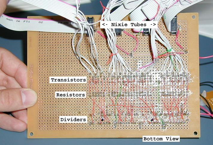 the bottom view |
well, it's been awhile since i actually did any work on this. once summer came and i actually had stuff to do outside, this got put on the back burner. but now i've moved cross country to new york city. and being that it's cold as hell here i've started up again. i did a little maintenance tonight, burned myself and the usual fun. hopefully i'll have some progress and new pictures here soon (not that anyone is reading this)...
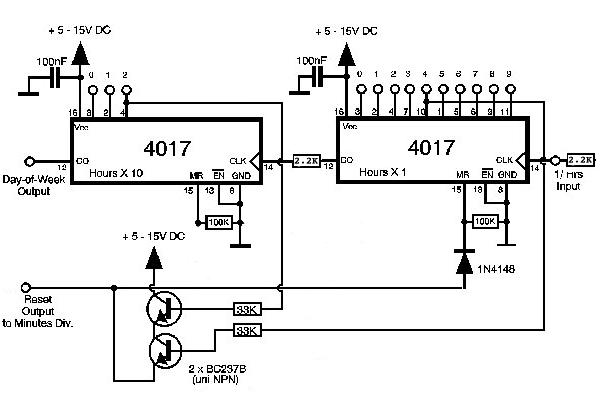
***this weekend i finally got the hour tubes installed. if we ever find the original drawings again (found 'em <g>) i'll alter the plan and show you what i did. but, until then i'll just give you a piece or two of advice.<g> in the original plan there is a circuit to zero the clock when it is turned on. you may notice that when you turn it on, it won't always be zero, and sometimes multiple numbers are lit until that tube rolls over.
the original
11/13/2005: it looks like there should be a diode running to pin 15 in both hour decade counter chips (4017s). if it's not there, the teens hour probably won't reset. i must have cut it out when redoing the picture and forgot to draw it back in. DOH!
***i left it out because i figured that i would always set the clock when i turned it on...and for some reason it's kind of neat. i also added a 2.2K resistor from the minutes -> the hours and from the single hours -> tens-of-hours. i found that if this wasn't done the numbers would change from time to time even if they weren't suppose to and the resistor helps force the circuit to ground so that it won't suffer this problem. if i wasn't so lazy i'd do it for the rest of the clock. but i'd have a lot of re-soldering to do if i did that.
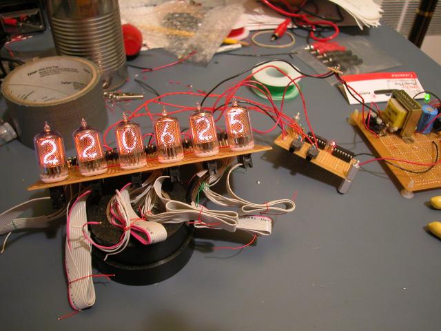 hours...minutes...and seconds |
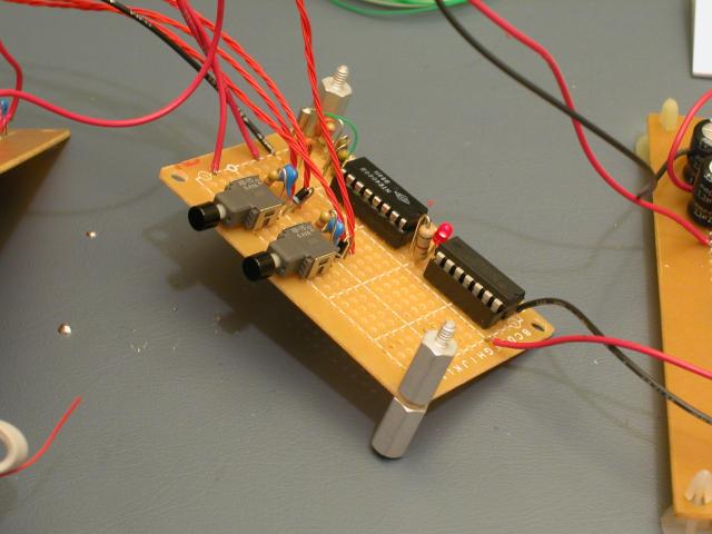 the timing circuit with clock setting switches |
***originally, i didn't implement clock-setting. i just put in a switch to change between 1hz and 8/16/32hz at the seconds. later, once i got done with the hours, i needed to add the clock setting function. to set the clock you can set the minutes and then the hours. the trick is that if you go past 59 minutes it carries over to the hours and if you go past 24 hours it resets the entire clock to 00:00:00. but, as long as you don't use a ultra fast speed (like i've tried) you won't have any problem.
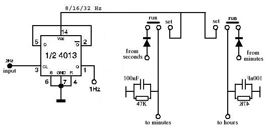
this is just a composite of the original timer and the clock setting diagrams.
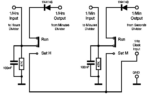
orignally, i only used the seconds to set the clock.
and a second nixie clock has begun...
| MOVIES: | ||||||||||||||||||||||||||||||||||||||||||||||||||||||||||||||||||||||||||||||||||||||||||||||||||
| from 53 to 54 seconds: 53to54.mov | ||||||||||||||||||||||||||||||||||||||||||||||||||||||||||||||||||||||||||||||||||||||||||||||||||
| from 14:59 to 15:00 (2:59pm & 3pm): 14to15oclock.mov | ||||||||||||||||||||||||||||||||||||||||||||||||||||||||||||||||||||||||||||||||||||||||||||||||||
| TIPS: |
||||||||||||||||||||||||||||||||||||||||||||||||||||||||||||||||||||||||||||||||||||||||||||||||||
| 1) you need to have some way to measure voltage and hz. i have a fluke 110 digital multi meter (dmm) that measures volts, hz, capacitance, resistance and a couple other things. it works great. this is very important as trouble shooting this stuff will be impossible without one. | ||||||||||||||||||||||||||||||||||||||||||||||||||||||||||||||||||||||||||||||||||||||||||||||||||
| 2) test along the way!!! if you build it all at once, you'll never be able to figure out where the problem is. test and troubleshoot along the way. | ||||||||||||||||||||||||||||||||||||||||||||||||||||||||||||||||||||||||||||||||||||||||||||||||||
| 3) to see if your crystal is oscillating don't measure on the crystal's circuit. this disrupts oscillation, even if it's going, and causes it to stop. test the pins of the 4060 to see if they are at the appropriate levels. | ||||||||||||||||||||||||||||||||||||||||||||||||||||||||||||||||||||||||||||||||||||||||||||||||||
| 4) get a SMALL soldering iron w/a stand. when working with all the litte wires on the bottom of a board it makes it so much easier to solder things in w/out burning other wires in the vicinity. you can get a weller stand, complete w/sponge, but these things will run you $50 or more. i picked up the radio shack special for $6.99. while not near as good, it keeps the pen off the floor, which is all i really care about. | ||||||||||||||||||||||||||||||||||||||||||||||||||||||||||||||||||||||||||||||||||||||||||||||||||
|
5) some part number translations that i found back when i started and need to write down somewhere
before i lose it. and, it might be useful for some.
Part #1N4148 = NTE-519 Part #BC237B = NTE-123AP Part #MPS-A42 = NTE-287 |
||||||||||||||||||||||||||||||||||||||||||||||||||||||||||||||||||||||||||||||||||||||||||||||||||
| looking for a new project? check out peter's nixie tube mini-tester looks cool... | ||||||||||||||||||||||||||||||||||||||||||||||||||||||||||||||||||||||||||||||||||||||||||||||||||
| CHANGES: | ||||||||||||||||||||||||||||||||||||||||||||||||||||||||||||||||||||||||||||||||||||||||||||||||||
| this page may be a bit hard to understand, so i'll post changes here so you don't have to re-read the whole things as little changes come about. i am by no means a good web-page developer...and it shows. | ||||||||||||||||||||||||||||||||||||||||||||||||||||||||||||||||||||||||||||||||||||||||||||||||||
| 6/4/2003: added the two movies above. careful though, my connection up-bound is slow and the movies are 3+MB each. | ||||||||||||||||||||||||||||||||||||||||||||||||||||||||||||||||||||||||||||||||||||||||||||||||||
| 2/11/2003: i got the links to peter's new page so i went through my page, updated links and added the hours diagram. | ||||||||||||||||||||||||||||||||||||||||||||||||||||||||||||||||||||||||||||||||||||||||||||||||||
| 2/9/2003: added hours and clock setting sections. note - peter wendt's page and diagrams seemed to have disappered, and as i haven't saved a copy of the original web page, i only have a print-out. so...some of the original diagrams referenced won't have a link to the original until he resurfaces. (i really need to learn how to use a camera) | ||||||||||||||||||||||||||||||||||||||||||||||||||||||||||||||||||||||||||||||||||||||||||||||||||
| 1/22/2003: added the new timeing circuit info along w/tip 5. | ||||||||||||||||||||||||||||||||||||||||||||||||||||||||||||||||||||||||||||||||||||||||||||||||||
| 8/19/2002: added pictures and added/changed the paragraphs with stars. | ||||||||||||||||||||||||||||||||||||||||||||||||||||||||||||||||||||||||||||||||||||||||||||||||||
| 4/30/2002: see tip #4, and two paragraphs with stars. | ||||||||||||||||||||||||||||||||||||||||||||||||||||||||||||||||||||||||||||||||||||||||||||||||||
| 2/13/2002: added the two pictures right after the 1hz generator. | ||||||||||||||||||||||||||||||||||||||||||||||||||||||||||||||||||||||||||||||||||||||||||||||||||
| 2/7/2002: added the 1hz generator picture with modifications. | ||||||||||||||||||||||||||||||||||||||||||||||||||||||||||||||||||||||||||||||||||||||||||||||||||
| 2/6/2002: started the page...it's all new! | ||||||||||||||||||||||||||||||||||||||||||||||||||||||||||||||||||||||||||||||||||||||||||||||||||
disclaimer: you are COMPLETELY at your own risk when trying to build anything referenced on this page. i am not your mom, think for yourself. if you can't, don't start the project.