|
7/2/2006:
a few years ago i got the hankering for some sort of an electronics project and my first
nixie clock was born. then, after a hiatus, i started the second clock and
actually have it in a box and running now. along the way i ran into these these things called dekatrons. one of
the best descriptions is on mike's page at
detailed description of a dekatron operation.
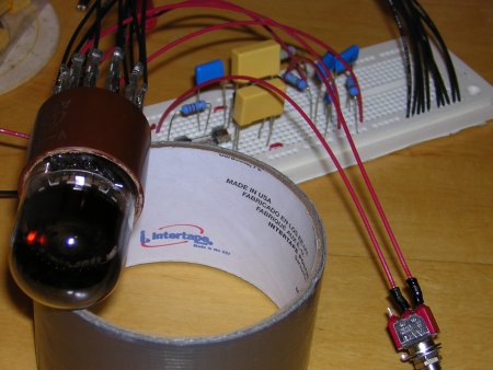
mmm...something rotating in circles. mesmorizing. and, in theory, it wouldn't take me months and months before i got something that actually worked, like with the clock. don't get me wrong, i LOVE my clocks. but, i want a project to poke around with that has a bit of a quicker turn around time. the plans that are referenced all over originally come from mike. in trying to find my dekatron tubes i went to sphere research (ya, i like these guys). i bought a pair of russian a101 tubes. since they're the a101 tubes i used the schematic from www.oflittleinterest.com. it's a fork from mike's plan for the a101, and it's very nice and easy to follow. <g> and with just a little bit of toying around on the plug board the initial run is a go!
i should note that since i live in the states i had to add a level to the voltage double and make it a voltage tripler. these movies do suck, but if you're lucky, you might be able to tell that i was able to get it to spin both clockwise and counter-clockwise by reversing the G1 and G2 connections on pins 5 and 10 respectively.  see it clockwise... see it counter-clockwise... now, what i'd really like to do is figure out how to get the tubes to spin at different speeds. a few people seem to have done it, but i haven't been able to find any schematics or diagrams. looks like i'm off to the drawing board! |

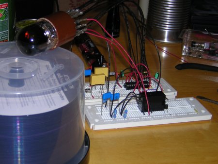
7/9/2006: no spinning at different speeds yet, but it changes from clockwise to counter clockwise by
itself via a 555 timer and relay. more details and a drawing to come...
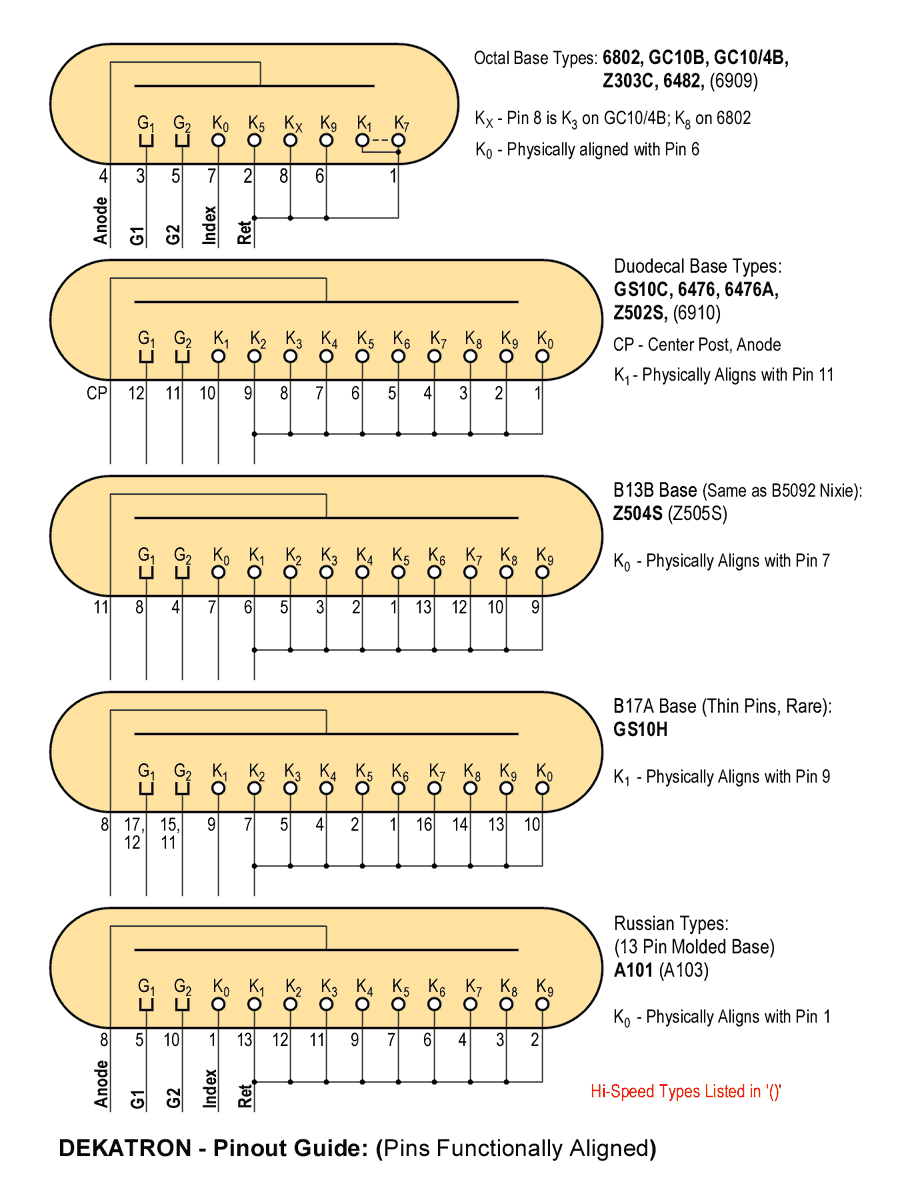
but, until then, a couple of links: i've found a great page talking about an 555 astable oscillator circuit diagram complete with a calculator for figuring stuff out. and here's a nice common dekatron pinout diagram that i found in archives of the NEONIXIE-L group based at yahoo compliments of mike moorrees. |
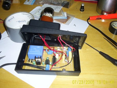
7/16/2006: the first run is a go! and by that i mean no more plug board an screwing around. i
ordered a few more pieces and soldered virtually everything together this weekend to get the
self switching clockwise/counter clockwise setup in motion. it's been pretty darn exciting...
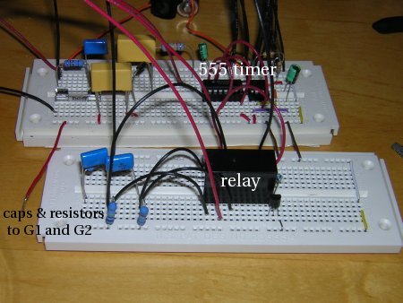
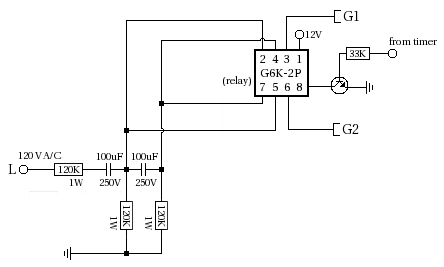
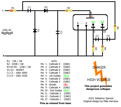
the relay is really pretty darn nice too. it's very quite and the click is no more than a tap, unlike the radio shack relay. once it goes in a box, you won't be able to hear it. the transformer is a bit big, i know, but honestly, i was lazy and didn't want to wait for a back order of a smaller one you can get. sad...i know. here is the power schematic for the voltage tripler i'm using: 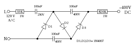 you can see that it takes 120V A/C in and triples it to around 400V DC. the output is then sent to the anode of the dekatron tube. note that it's important, and this is from mike's site, that you have the 33K 1W resistor before and 820K 1W resistor afterward. also note the L and N for the A/C. if you don't know how to decipher this, make sure you look into it as it's important. and then we have the voltage regulator for the timing circuit: 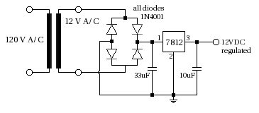 it uses a transformer to change the 120V to 12V and then a full wave bridge rectifier and voltage regulator to change it to DC and make sure that the voltage is stable. maybe you don't need to actually have the voltage regulator, but it seems that when dealing with ICs it's good to make sure that you have a nice even, steady voltage. then, we have the timing circuit. (i know i've left some stuff out...it's coming)
it'll make more sense when i get the relay circuit up, but basically it's in control of switching the relay. R1, R2 and C1 determine thus determine length of clockwise and counter-clockwise spin. you can use the calculator above or my little table for reference, even though it's not very useful. <g> i'm actually using 47K, 94K and 33uF for about 5 seconds of spin in each direction. i like it like that... |
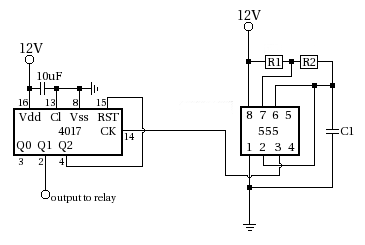
7/23/2006: and finally, the relay circuit:
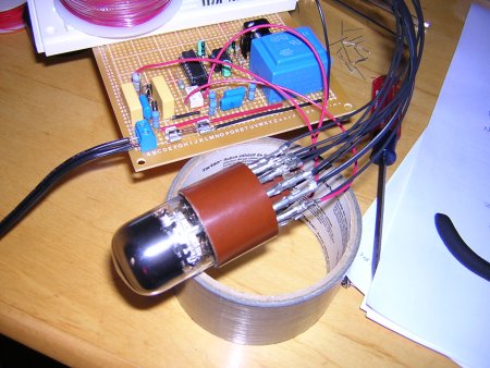
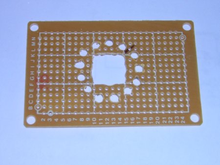
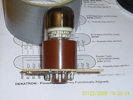
so, if you string all of these together into a russion a101, you've got the dekatron clock-wise, counter-clockwise rotation circuit that i've been playing with. the one trick, that isn't pictured, is the fuse. at the point where the N A/C line input connects, i have a 100 mA slow blow fuse. i got this from dieter's B13B and K8A circuits. it's a good protection to build into this, as you probably don't want 15-20 amps running through your circuit if you have a short or other problem somewhere. <g> i've actually only put one other project into a box, the nixie clock, and i wanted to try it again before moving on to the next step. but, with the a101 the hardest part seems to be finding a socket. i think it's pretty much impossible...although i know someone will read this and think "ya, i have 100 of sockets that work just fine". oh well... so, i attempted to make one from a pcb that i would then solder the tube too hopeing that it would not fry the tube.
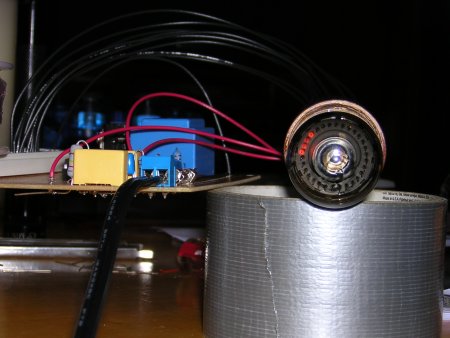
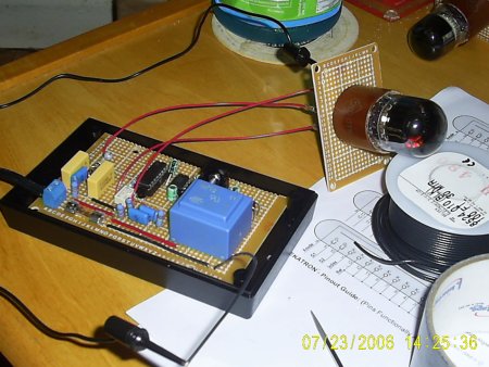
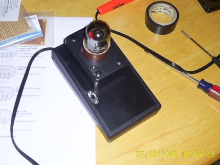
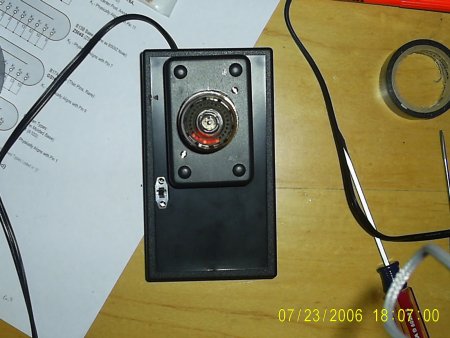
soldering everything together is the real question. i just didn't know if it would kill the tube or not. but, i may have just been lucky as both tubes i have i put in the pseudo-socket and they tested out just fine afterward. yay! (and there was much rejoicing!) so, why do this? afterall, they won't be able to be removed from the pseudo-socket for quick change or the like, right? in this case it's strictly for mounting purposes. in boxing everything up there needs to be a way to hold the dekatron to something and this was the best way i could some up with without an actual socket. since the dekatron is now soldered to the pcb, the pcb can now be screwed into whatever you want so that the tube will be anchored. and, since it's mostly for show, and not for real use, the hope is that the tube will have a long enough life span that it won't need to be changed. and if so, once could be done...but it won't need to be done often, so you get the picture. and the first run looks like...
i know you're wondering why the tube is mounted inside the little box on top of the bigger, sloped box, right? it's because the transformer, along with the bottom of the dekatron, won't fit inside the sloped box. it's just a bit too small. so i mounted this small box on top to give the extra room for the transformer and the dekatron. if i had gotten the 42mA transformer, it all probably would have fit without the need for the extra space. so, there's the first run...now, back to the drawing board. <g> |

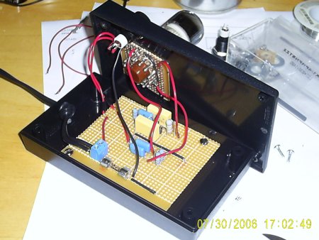
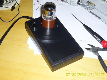
7/30/2006: and i decided to put together a second one with another a101 tube i have. this one is based only
the design from the plans i mentioned above. if you're really, really wondering though,
i used the tripler and the normal G1 and G2 driver. that's it...
|
|
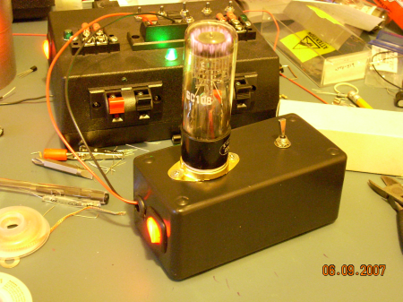
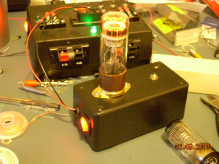
6/9/2007: and after much downtime and a move from one coast to another i decided it was time
to work on something again. granted, it's just a small little project, but more like "getting my
feet wet" as i haven't done much in awhile. anyway, i've a few gc10b style dekatrons and i've been
trying to figure out what kind of socket to use. the pages of dekatons and sockets at tube-tester.com
has a ton of great information but trying to find the k8a socket has been, well, unproductive. i've
heard rumored that the generic octal sockets fit the dekatrons so i found a local surplus store
and took one of my tubes over to see what would fit, and by-howdy, the generic, gold plated octal
socket for $3.50 worked! very excited was i. <g>.
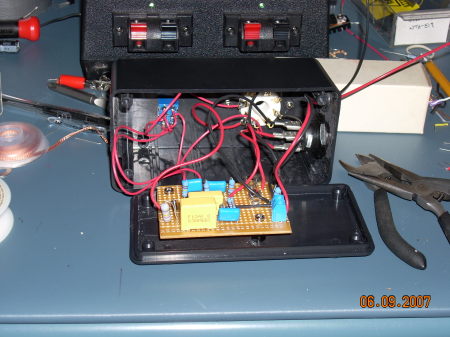
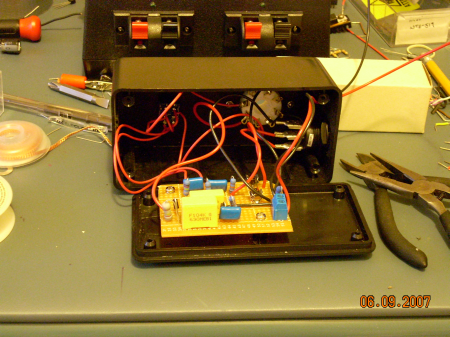
with sockets for the tubes i just had to build something! so i decided to build a little test unit with a little switch so i could test both directions on each dekatron. like above, the 60hz rotation piece is based on mike's design and the 400+V DC powering the dekatron is a voltage tripler. other than that, it was just trying to figure out how to fit everything in the case and make it work. sometimes, the hardest part...
woo-hoo! |
- for the KA7812 voltage regulator used: KA-KA7812AE.pdf
- for the trans-era, apparenlty now pulse, transformer bv-030-xxxx: specifically, because i used bv030-7258 and it's in there.
- for the omeron relay: D20G6K0305.pdf
disclaimer: you are COMPLETELY at your own risk when trying to build anything referenced on this page. i am not your mom, think for yourself. if you can't, don't start the project.