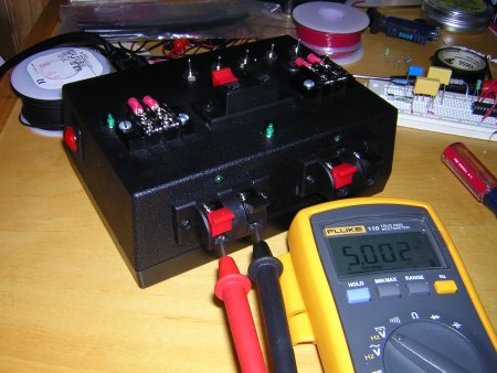
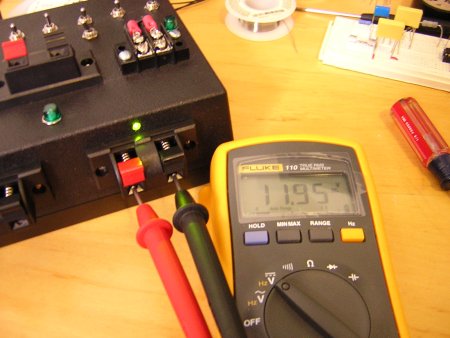
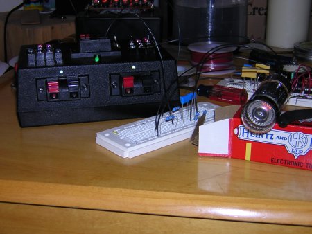
In the days of playing with nixie tubes, dekatrons, 555 timers, LEDs, and what-not over the past six years I've had to find some way to power all this stuff. Once in awhile it's easier than expected. After all, LEDs and the timing circuits in nixie clocks can run off 5 or 12 volt DC power so you can just use batteries. The nixie tubes and dekatrons, however, require a little more umpf, and 140V or 400+V DC is a little hard to come by on the battery only side. On top of this, from time to time, I have spent more time figuring out why the circuit does not have a good connection to the batteries and there is no power supplied, instead of playing with what I wanted to when I began the endeavor. So, I decided I would build a devel power supply that would give me 5V DC, 12V DC, 110V A/C, 220V DC and 440V DC so I could stop worrying about this and have a nice way to power things while I was learning how everything worked. There were a couple of goals...more or less met. Keep in mind that this is the first one built, so you'll undoubtedly see a few places it could be improved and and maybe some things that need fixing here or there. but, we'll see how it goes...
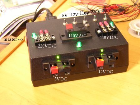
so, did we do it? yup...or at least i think so. <g> these may all just be things that are taken for granted, but since I'm relatively new and this is only my fourth boxed project I wanted to make sure it solved a lot of problems that could arise if I hurried to quickly and would make sure that the devel power supply would be very usable in the future and not cause problems. so, how were the above addressed?
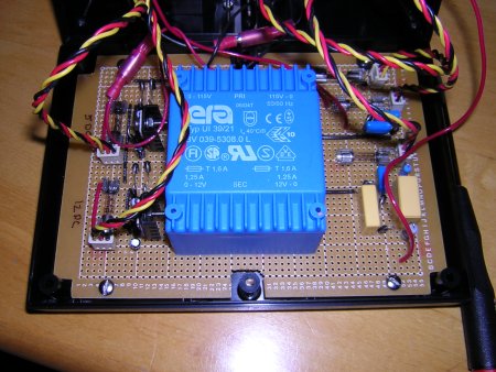
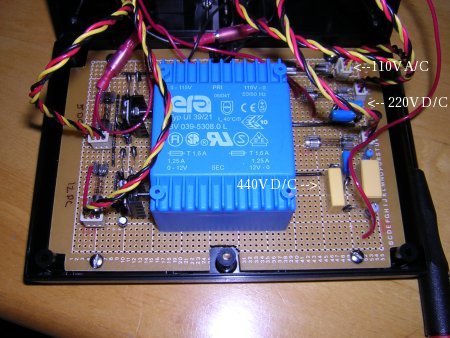
so, hopefully this makes sense to someone besides me. the 5 and 12 volt are voltage regulated and pull from a HUGE, seriously, transformer from a company formally know as trans-era now know as Pulse. It takes 110V and spits out 12V on a secondary 1 and secondary 2 that can each draw at 1amp when wired the way it currently is (see the doc below). Here's the schematic I created and built from: 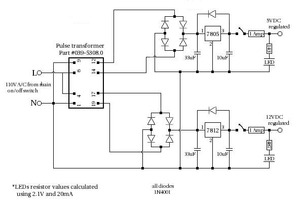
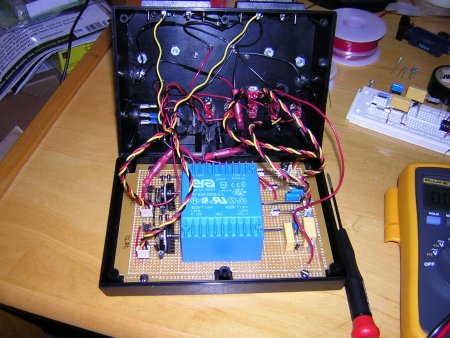
The 110V A/C comes directly from the line, so it's actually whatever your line is. The 220V and 440V use a voltage doubler and tripler, so the output could vary a bit since there's no regulation and I have seen A/C vary anywhere from 110V - 135V or higher. Remember that when building this you need to carefully short the capacitors in the voltage doubler and voltage tripler as they hold their charge after the power has been turned off. If you do not do this, then you risk shocking yourself with the high voltages contained within the capacitors. Note: I didn't actually put the jumper in for measuring current, but it seems like an interesting idea, so i left it in the schematic. Here's the schematic I created and built from: 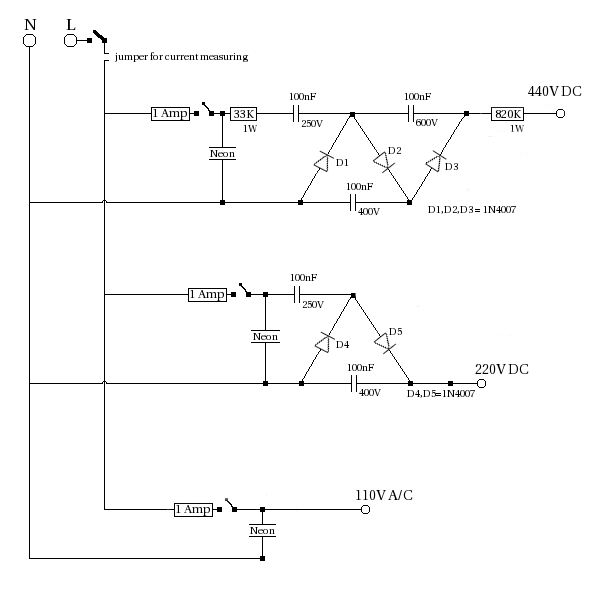
So how does it work?
and testing dekatrons is much, much easier now. not to mention that the connections to the power supply are just a tad bit more reliable. "what is he talking about?" you may be asking....well, I won't even go into it. Let's just say that in the past I've wasted a bit of time with bad connections to the power supply. project built: 9/17/2006 page updated: 9/17/2006 | ||||||||||||
- Trans Era (now Pulse) 12V/1250mA doc